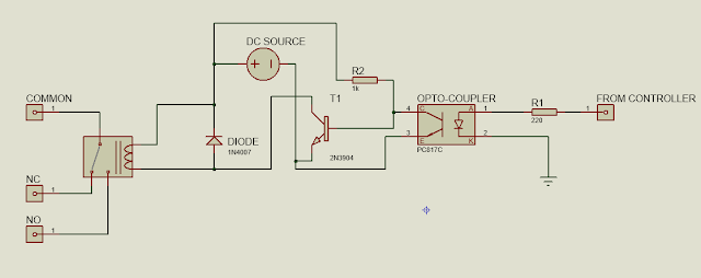
Triggering circuit for relay (SPPT) Using Microcontroller
To control the operation or state of relay, an external control
circuitry is required. This circuitry control the flow of current through the
coil of relay and hence change the state of relay. Figure 1 shows the
triggering circuitry for the relay. As we are using microcontroller for the
control of whole circuit, so we designed a circuit such that it can trigger the
relay by the pulses generated by controller.
Figure 1: Triggering
circuit for Electromagnetic relay
Now, lets check the working of this circuit.When
logic 1 is applied from controller, a high signal gets applied at the base of
transistor. Transistor act as closed switch and dc voltage drop across the
diode(reverse biased) and small current flows through the coil of relay,
because it is in parallel with the diode. In this way relay gets triggered and
common terminal gets connected with NO terminnal. When logic 0 is applied from controller, logic low gets
applied at the base of transistor and transistor act as an open switch. All the
dc voltage gets drop across transistor and no current flows through the coil of
relay. Hence by generating logic high and low from microcontroller, we can
control the state of relay.
Transistor 2N3904, diode 1N4007 and opto-coupler
PC817 is used in this circuit. You can consult their datasheet for their
configuration and characteristics. These are the low cost component available
in the market. Because swtching frequency of electromagnetic relays are usaully
upto 1KHz, and triggering circuit has low operating voltage. So, we don’t need
high frequency and high voltage or
current rating component.
DC volatge for Relay Operation
As shown in Figure 1, the triggering circuit for
relay requires constant dc voltage source but there is no source of dc voltage
in our circuit for relay and other components because,we are doing ac
regulation and only input ac voltage is present. So, we have to convert ac
voltage into constant dc volatge. This is done by using step down transformer
having turns ratio of 0.04. This transformer can convert 220V into 9V RMS ac
voltage.The peak value is Underwood 2 times of rms value so peak will be 12.7V. Full wave rectifier and filter capcitor for smoothing is used at the
secondry of transformer. In this way,we have converted ac input voltage into
low level dc voltage.To maintain constant dc volatge, linear regulator LM7812
can be used. Complete circuit for the conversion of ac into dc is shown in
Figure 2.
Triggering circuit for relay (SPPT) Using Microcontroller
 Reviewed by Unknown
on
September 16, 2017
Rating:
 Reviewed by Unknown
on
September 16, 2017
Rating:


No comments