Hardware and Software Implementation of AC Regulation Using Electromagnetic Relays
Hardware
The
actual hardware of regulatory circuitry is shown in figure 1. The detail of
each component used in this circuit has already been described in previous
articles.

Figure 1:
Actual hardware of the regulatory circuitry
Figure 1 does not show the measuring circuit
and dc converter circuit for relays. The complete setup for electromagnetic
relay technique is shown in figure 2. The setup is flexible and easy to debug.
Two knobs are present at the output to do power quality analysis of this
technique.

Figure 2:
Complete hardware setup for electromagnetic relay technique
Software
Microcontroller
STM32F407 is used for the generation of control signal and sensing. Programming
is done on MATLAB Simulink, compatible with the controller. Figure 3, shows
the block programming done for this technique.
Description
of each block used is given below:
- Target block, setup Simulink for STM microcontroller
- Regular ADC block is used for the sampling of analog signal to convert it into digital signal
- As the output put of ADC block is 16 bits’ raw data, to convert it into meaningful value, divide its raw value with 4096 and multiply with the reference voltage of controller
- Constant block is used to make constant variable of any type
- Compare block is used to compare some value with some constant
- NOT and AND blocks are used to implement NOT and AND logic
- Digital output block is used to get digital output at any pin of controller
- Analog
signal is first converted to digital signal which is then compared with
constants to generate desired pulses. At any instant of time, only one pin is
at digital high.

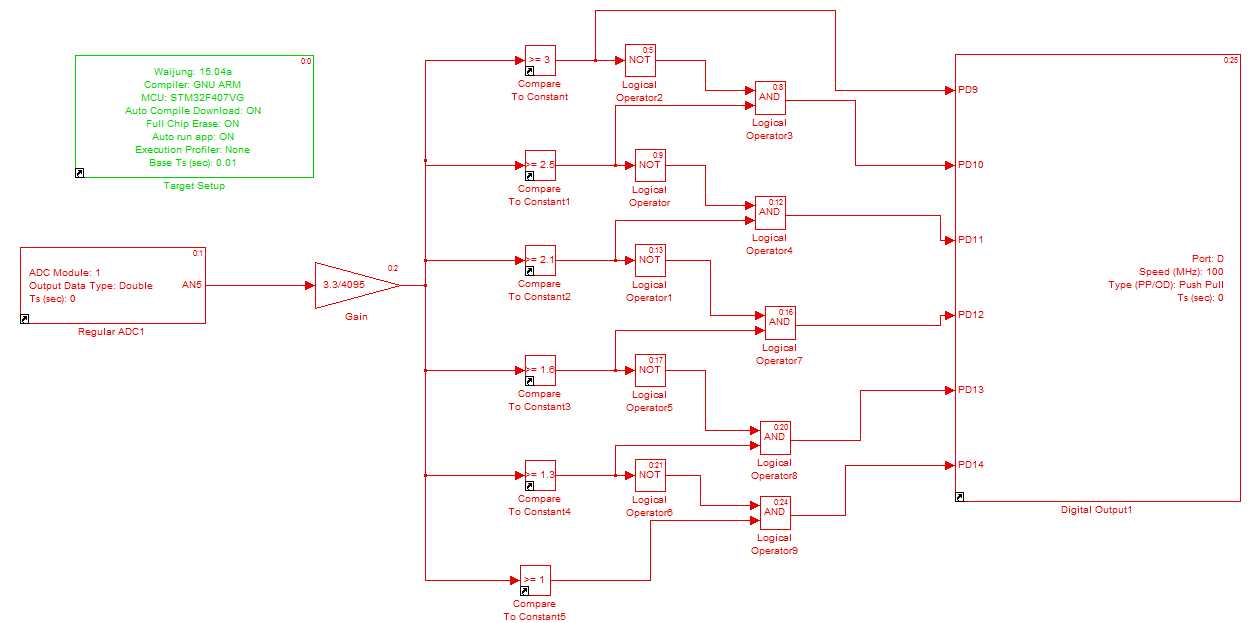
Figure 3:
MATLAB (Simulink) Block Programming
Hardware and Software Implementation of AC Regulation Using Electromagnetic Relays
 Reviewed by Unknown
on
September 17, 2017
Rating:
Reviewed by Unknown
on
September 17, 2017
Rating:
Reviewed by Unknown
on
September 17, 2017
Rating:

No comments